
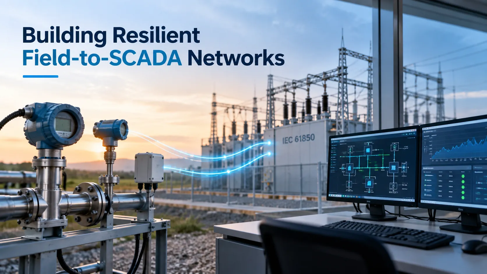
Substation SCADA automation in Saudi Arabia requires bridging process instrumentation with electrical protection systems over deterministic, hardened communication backbones. Achieving compliance with Saudi Electricity Company (SEC) standards and IEC 61850 demands converting analog field signals via smart remote terminal units (RTUs) and ruggedized Ethernet switches into Sampled Values (SV) and GOOSE messaging. This architecture delivers deterministic sub-4 millisecond fault isolation, automated telemetry ingestion, and continuous asset visibility across harsh desert operating environments.
The Engineering Challenge: Field Instrumentation in Extreme GCC Operating Environments
Operating process instrumentation and electrical switchgear in Saudi Arabia presents severe mechanical and thermal design challenges. Ambient summer temperatures in Jubail, Dammam, and Riyadh routinely exceed 50°C, pushing enclosed cabinet temperatures beyond 70°C. High humidity and airborne saline drift across the Arabian Gulf coast accelerate galvanic corrosion on terminal blocks, enclosures, and sensor diaphragms. Fine silica dust (desert sand) penetrates unsealed enclosures, blinding optical ports and clogging mechanical flow elements.
At the same time, the convergence of Operational Technology (OT) demands that process telemetry from field devices feeds directly into high-voltage electrical automation systems. Legacy field devices relying on isolated 4-20 mA current loops, HART loops, or Modbus serial links create significant engineering friction when interfaced with modern IEC 61850 digital substations. If your field-to-SCADA network drops packets during an upstream electrical disturbance, protective relays trip unnecessarily, resulting in costly plant downtime.
To maintain continuous availability across heavy industrial facilities, you must implement unified, ruggedized architectures. Deploying certified substation SCADA automation ensures your electrical protection, process controls, and field instruments operate synchronously on a fault-tolerant network.
Network Architecture: Bridging Process Instrumentation to Digital Substations
Integrating field measurement devices with electrical protection architectures requires a three-tiered network hierarchy: the Process Level, the Bay Level, and the Station Level.
1. The Process Level: Sensors and Merging Units
The process level contains primary physical equipment: current transformers (CTs), voltage transformers (VTs), temperature transmitters, pressure sensors, and flow meters. In a digital substation, conventional analog outputs from CTs and VTs connect directly to Merging Units (MUs). The MU digitizes instantaneous analog values into standardized Sampled Values (SV) data packets governed by IEC 61850-9-2.
For process process loops (such as cooling water flow to transformer heat exchangers or fuel pressure in gas turbine plants), high-accuracy sensors and instrumentation translate process variables into digital streams via HART-enabled I/O or native fieldbus interfaces, eliminating ground-loop interference.
2. The Bay Level: Protection, Control, and Conversion
Bay-level Intelligent Electronic Devices (IEDs), such as Siemens SIPROTEC or ABB Relion units, ingest process-level SV packets and discrete status points. The bay level executes local protection schemes, breaker monitoring, and interlocking logic.
Legacy serial sensors and Modbus RTU devices connect here via protocol gateways or smart RTUs. These gateways map classic Modbus holding registers into IEC 61850 Logical Nodes (e.g., mapping pump bearing temperatures to Logical Node STMP or flow rates to MMXU).
3. The Station Level: Human-Machine Interface and Centralized Telemetry
At the station level, redundant SCADA servers, engineering workstations, and historians interface with bay-level IEDs using IEC 61850-8-1 MMS (Manufacturing Message Specification). MMS operates as a routable client-server protocol over TCP/IP, allowing SCADA software to poll diagnostic points, update settings groups, and log sequence-of-events records with millisecond precision.
Mission-Critical Protocols: GOOSE, Sampled Values, and MMS
IEC 61850 replaces point-to-point hardwired copper circuits with high-speed packet-switched Ethernet communications. Successfully deploying this standard requires isolating three primary protocol types across your local infrastructure.
Generic Object-Oriented Substation Events (GOOSE)
GOOSE handles time-critical protection signals, such as trip signals, intertripping, and reverse interlocking.
- Operates directly on the Ethernet Data Link Layer (OSI Layer 2), bypassing TCP/IP overhead.
- Transmission latency remains under 4 milliseconds, outperforming mechanical interposing relays.
- Uses retransmission bursts: when an event occurs, the IED transmits identical packets repeatedly at escalating intervals ($T_0, T_1, T_2$) to guarantee packet delivery without handshake delays.
Sampled Values (SV)
Specified under IEC 61850-9-2 (and the IEC 61869-9 standard), SV digitizes continuous electrical currents and voltages.
- Merging units sample waveforms at strict, synchronized rates (e.g., 80 samples/cycle for standard protection and 256 samples/cycle for power quality metering).
- Because SV traffic consumes significant bandwidth (~5.6 Mbps per standard stream on a 50 Hz grid), it requires dedicated process buses or strict Layer 2 VLAN tagging to prevent switch port saturation.
Manufacturing Message Specification (MMS)
MMS manages non-time-critical monitoring, historical archiving, operator control commands, and disturbance record retrieval.
- Operates over OSI Layer 7 using standard TCP/IP port 102.
- Provides full semantic modeling of the substation equipment, eliminating arbitrary register maps common in Modbus protocols.
Hardening the OT Network: Industrial Ethernet Requirements
Standard commercial switches fail quickly under high electrical switchgear transients, electromagnetic fields, and Saudi ambient temperatures. Building a dependable substation communication network requires deploying hardened network and IT infrastructure compliant with IEC 61850-3 and IEEE 1613 specifications.
Essential Hardware Specifications
- Thermal Endurance: Convection-cooled components rated for continuous duty from -40°C to +85°C, eliminating failure-prone motorized fans.
- Electromagnetic Immunity (EMC): Certified immunity against electrostatic discharge (IEC 61000-4-2 Level 4), electrical fast transients (IEC 61000-4-4), and magnetic fields (IEC 61000-4-8).
- Power Supply Redundancy: Dual universal high-voltage inputs (88-300 VDC / 85-264 VAC) connected to isolated station battery banks.
Zero-Packet-Loss Network Redundancy (PRP and HSR)
Standard Spanning Tree Protocols (RSTP, MSTP) require 1 to 3 seconds to recover from a fiber link break. In high-voltage protection schemes, a drop of even 10 milliseconds can cause catastrophic breaker failure. IEC 62439-3 defines two zero-millisecond recovery standards:
- Parallel Redundancy Protocol (PRP): Dual-homed source nodes transmit two identical copies of every packet across two completely independent, parallel Ethernet local area networks (LAN A and LAN B). The receiving node ingests the first packet that arrives and automatically discards the duplicate. A complete failure of LAN A causes zero lost packets and zero failover time.
- High-availability Seamless Redundancy (HSR): Nodes connect in a physical closed loop. Every packet is framed with an HSR header and transmitted in both directions around the ring. The destination accepts the first arriving packet and discards the redundant twin.
Technical Comparison: Substation Communication Protocols
| Technical Parameter | IEC 61850 (GOOSE) | IEC 61850-8-1 (MMS) | Modbus TCP | DNP3 (Secure Auth v5) |
| OSI Layer | Layer 2 (Data Link) | Layer 7 (Application) | Layer 7 (Application) | Layer 7 (Application) |
| Transport Layer | Direct Ethernet (No IP) | TCP/IP (Port 102) | TCP/IP (Port 502) | TCP/IP or UDP (Port 20000) |
| Transfer Speed / Latency | < 3 to 4 ms | 20 to 100 ms | 50 to 200 ms | 30 to 100 ms |
| Deterministic Response | Yes (Priority Tagged) | No (Best-effort TCP) | No | Limited |
| VLAN / Priority Support | Yes (IEEE 802.1Q/p) | Supported via switch | Supported via switch | Supported via switch |
| Data Structure Model | Self-describing SCL | Object-oriented model | Flat register tables | Object-oriented points |
| Cybersecurity Baseline | IEC 62351-6 (Digital Signatures) | IEC 62351-4 (TLS encryption) | None (Requires VPN) | IEC 62351-3 / 5 (Built-in Auth) |
| Primary Industrial Use | Trip signals, interlocking | SCADA telemetry, trends | Process instruments | Remote telecontrol (RTU/WAN) |
Step-by-Step Engineering Lifecycle: Field-to-SCADA Deployment
Deploying integrated field and substation control architectures requires an organized, rigorous engineering process to satisfy plant safety standards.
Phase 1: Substation Configuration Language (SCL) Modeling
The integration begins in software using engineering tools that comply with IEC 61850-6.
- The Substation Specification Description (.SSD) file is authored, defining single-line diagrams, voltage levels, and primary equipment.
- IED Capability Description (.ICD) files are gathered from switchgear protection relays and instrument gateway manufacturers.
- The System Configurator compiles these inputs into a master Substation Configuration Description (.SCD) file, locking in all GOOSE subscription datasets, SV publisher addresses, and MMS server allocations.
Phase 2: Instrument Selection and Hazardous Area Classification
Field instruments deployed in hydrocarbon or chemical processing facilities across Saudi Arabia must maintain proper safety approvals.
- Select instruments bearing ATEX / IECEx Zone 1 and Zone 2 certifications (Ex d explosion-proof or Ex ia intrinsically safe).
- Specify sensor wetted parts using Hastelloy C-276, Monel, or 316L stainless steel to resist sour service ($H_2S$ exposure) under NACE MR0175/ISO 15156 standards.
Phase 3: Network Provisioning and VLAN Separation
To protect deterministic protection streams from network congestion, configure switch ports with strict quality-of-service parameters:
- Assign dedicated VLAN IDs for GOOSE messaging (VLAN Priority 6 or 7).
- Create separate VLAN IDs for Sampled Values streams to confine high-bandwidth multicast data.
- Enable IGMP Snooping and static multicast filtering to prevent switches from broadcasting GOOSE and SV packets out to unrelated ports.
- Configure IEEE 1588v2 Precision Time Protocol (PTP) boundary or transparent clocks on all switches to synchronize devices within 1 microsecond.
Phase 4: Factory Acceptance Testing (FAT)
Before onsite delivery, the complete system must undergo hardware-in-the-loop validation:
- Connect all protection IEDs, Ethernet switches, and field gateways in a controlled testing bay.
- Inject simulated secondary currents and voltages using OMICRON or Megger test sets to verify SV processing.
- Trigger protection trip logic and record GOOSE propagation times using network analyzers (such as Wireshark configured with IEC 61850 dissectors) to verify sub-4 ms latency under full network traffic loads.
Phase 5: Site Acceptance Testing (SAT) and Live Commissioning
The final phase validates field operations at your Saudi facility:
- Verify instrument calibrations against physical standards.
- Confirm polarity and loop integrity for all hardwired inputs terminating at marshaling cabinets.
- Perform high-voltage insulation tests, primary injection tests, and full protection trip checks on breakers.
Regulatory and Standards Compliance in Saudi Arabia
Industrial facilities across the Kingdom must satisfy both local safety codes and international interoperability standards.
| IEC 61850 / IEC 62439-3 | International Interoperability & Redundancy |
| SEC Transmission System | TES-P-119 Standards (Substation SCADA & RTUs) |
| Saudi Building Code 601 | Energy Conservation & Electrical Automation |
| SASO Certification | Mandatory Safety Clearances for Low/Med Voltage |
| IEC 62443 / NCA ECC-1:2018 | Cyber Security Controls for Critical Systems |
- SEC Standard Specifications: Switchgear telecontrol and automation systems must conform to Saudi Electricity Company standards (including TES-P-119), ensuring RTU protocols communicate cleanly via DNP3 or IEC 60870-5-104 with central dispatch centers.
- Saudi Building Code (SBC 601 / SBC 401): Mandates specific electrical installation rules, metering interfaces, and automated electrical efficiency metrics across commercial and industrial campuses.
- SASO Conformity: All imported and locally assembled switchboards, marshaling cabinets, and control panels must hold valid SASO certificates based on IEC 61439-1/2 type tests.
- National Cybersecurity Authority (NCA ECC-1:2018): SCADA and OT networks governing essential infrastructure must enforce perimeter firewalls, role-based access control, disabled unused switch ports, and continuous network intrusion monitoring.
Frequently Asked Questions
What are the main differences between hardwired I/O and IEC 61850 GOOSE messaging?
Hardwired connections require individual multicore copper cables routed between field switches, interposing relays, and input cards, introducing propagation delays and points of physical failure. IEC 61850 GOOSE transmits digitized status signals across shared, redundant Ethernet fiber optics in under 4 milliseconds, providing automated network supervision and continuous cable-break monitoring.
Can legacy Modbus RTU sensors communicate with an IEC 61850 substation SCADA system?
Yes. You can install an industrial gateway or a smart RTU at the bay level. The gateway reads Modbus holding registers over RS-485 serial loops, converts those data values into IEC 61850 logical nodes (such as MMXU or GGIO), and exposes them to the station bus as MMS or GOOSE data sets.
Why is IEEE 1588 PTP preferred over NTP or SNTP in digital substations?
Standard NTP and SNTP protocols offer time synchronization accurate only to within a few milliseconds, which is insufficient for digital sampling. IEEE 1588v2 Precision Time Protocol (PTP) provides sub-microsecond synchronization ($< 1\,\mu\text{s}$) directly at the hardware layer, which is strictly required to correlate phase angles across Sampled Values streams.
What is the maximum latency permitted for a GOOSE trip command under IEC 61850?
Under IEC 61850-5 (Performance Class P1/P2), the total transmission time for critical trip messages must not exceed 4 milliseconds. This budget includes internal processing within the sending IED, network switch transit times, and message parsing by the receiving breaker controller.
How does Parallel Redundancy Protocol (PRP) prevent data loss during switch failures?
PRP operates by equipping devices with two independent network ports that transmit identical data packets simultaneously across two separate, uncoupled Ethernet networks. If an industrial switch or fiber link fails on one network, the receiving device processes the packet from the alternate network without dropping data or waiting for failover negotiation.
Engineering Next Steps: Consult with SAS Technology
Building a reliable field-to-SCADA architecture demands deep domain experience across primary switchgear, field instrumentation loops, and industrial networking topologies. SAS Technology designs, manufactures, and integrates end-to-end automation infrastructure built to withstand the harshest operating conditions in the Middle East.
Contact our engineering team to review your substation modernization requirements:
- Headquarters: Dana Towers, Al Khobar, Saudi Arabia
- Direct Engineering Support: +96 6506051781
- Technical Inquiries: info@saselectrotech.com | sales@saselectrotech.com
- Schedule a Consultation: Contact SAS Technology
